|
|
 |
|
|
|
The ATXbench-top power supply adapter board:
A very useful board, simple and elegant, allows you to convert any standard ATX computer power supply into a perfect supply for breadboarding and general electronics workbench use.
So, why not just put a bunch of banana jack binding posts directly on the power supply, as I've seen so many people do across the web??? Good question! Here's why:
- ATX PSUs are designed with extremely tight clearances inside them. If you go putting binding posts in there, you may be closing in on safety clearances (and these are important - the mains input side of most switching supplies see voltage spikes up to 1000+ volts, and DC busses around +370 volts. It's not worth risking life and limb!)
- You have a perfectly good computer power supply, and if you're anything like me you may want to use it to power op-amps one day, and a computer motherboard the next - why modify it beyond it's original use?
- You still need a soft-switch circuit.
- ATX power supplies have built-in protection, but there's also a Power Good output that tells the motherboard when the PSU is ready, or if there's a fault condition. It would be nice to have this displayed on an LED.
This ATX adapter board offers all these features, has standard 0.75" jack spacing for dual-banana plugs, and has color-coded binding posts for each of the voltage rails: 5V standby, 3.3V, 5V, +12V, -12V. This project comes as a complete kit, with the PCB, all components including binding posts, components, and ATX connector, plus comprehensive assembly instructions which includes the schematic diagram and PCB assembly diagram, as well as drill templates for panel mounting.
Price of PCB only: $16 USD
Price of complete kit: $30 USD ($7 shipping to USA, $24 ROW, $12 for the slowest option - you can thank USPS for their recent price hike on international shipping!)
Discounts for volume purchases are available - please email for details.
YOU MUST ADD YOUR INTERNATIONAL PHONE NUMBER or you might have problems with your shipment in CUSTOMS. It is best to have your phone number automatically added through PayPal but just in case please enter it below.
Choose the correct shipping option from the pull-down list:
Choisissez l'option correcte d'expédition à partir de la liste déroulante:
Wählen Sie den richtigen Versand-Option aus dem Pull-Down-Liste:
Piliin ang tamang opsyon sa pagpapadala mula sa pull-down na listahan:
Scegliere l'opzione di spedizione corretto dall'elenco a discesa:
|
|
Read the full original article below:
This one ain't exactly DSP, but it sure is useful!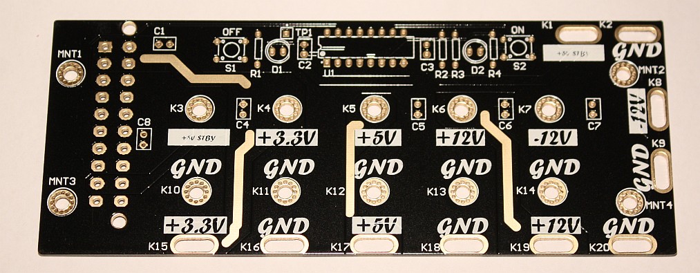
Let’s start with the basics: for any electronics or embedded system tinkering, you have to have a good power supply. Now I don’t know about your personal lab equipment budget, but mine is rather, well… let’s just say that I’m married to the head of the finance department, and she’s not exactly an electronics engineer. If you’re anything like me, you’ve probably crafted a few linear regulated power supplies over the years, but it’s no trivial task to design and build a variable high powered lab supply. And also, if you’re anything like me, the majority of what you tinker around with is digital circuits and low-voltage analogue stuff, like audio preamp
s and such.
In most cases, I am messing around with a microcontroller and a few opamps, so typically it’s handy for me to have a 5V rail for the micro (and any glue logic I might have), and +/-12V rails for the opamps. Increasingly, the sample devices I’m working with (for example, the Freescale DSP56367 DSP, or the NXP LPC2101 ARM-7 microcontroller) require low voltage rails for internal core and IO, namely 1.8
V and 3.3V. This is a pain in the butt if you’re having to build a supply with all these rails for each project, but most of them (except 1.8V) can be obtained from off-the-shelf PC ATX switching power supplies. This is great, because somehow (I don’t exactly know how) over the years I have accumulated several of them. They all have 3.3V, 5V, 5V Standby, +/-12V supply outputs.
Granted; on many, cross regulation of the 12V rails is not fantastic. For the vast majority of opamp circuits it is more than adequate. I have seen others converting ATX power supplies to benchtop lab supplies and putting minimum load resistors in them – in my experience this is not necessary since the cooling fan is generally enough of a minimum load, and most modern switching power supplies are designed to run down to zero load anyway. I thought I’d give it a go – I need to volts and these are just lying around.
One thing I didn’t want to do was simply hack up ATX cases to put binding posts on them, for a few good reasons:
-
You could really be messing with safety clearances inside the case. I don’t want to risk getting electrocuted because of the location of the 5V binding post output.
-
I want the ATX supplies to remain ATX supplies – there is a chance I’ll want to actually plug them into a motherboard again at some point, so I don’t want to hack off the ATX connector.
-
I wanted a more elegantly designed solution, that had not only the binding posts, but also some clip points I could clip alligator leads onto.
So I set about designing a PCB for adapting the ATX supply to benchtop use. As with anything, a good place to start are some specifications.
The adapter shall:
1. not alter the power supply itself,
2. use an ATX connector,
3. have binding posts for each ATX power supply voltage and standby,
4. have a matching return (GND) binding post for each voltage output,
5. be capable of handling heavy supply currents,
6. have a switch circuit to make use of the ATX on/off controller,
7. have LEDs to monitor standby and Power Good signal, and
8. use through-hole PCB design so you, dear reader, can make one for yourself easily.
I had also considered a built-in panel meter so you could monitor the output voltage of each output, but quickly realized this would be unnecessary feature-creep for this, since the outputs are fixed and fairly well regulated, and most users (like me) can plug in their multi-meter and get a more accurate measurement anyway.
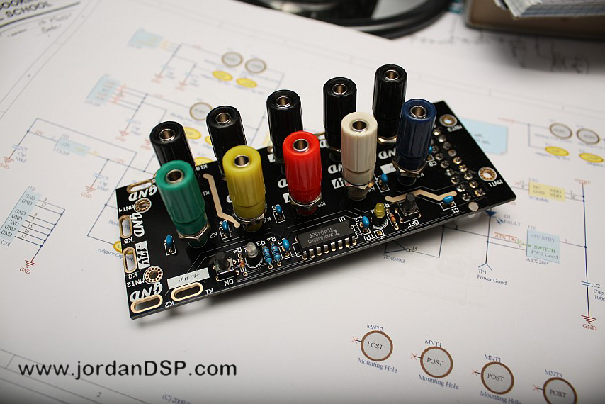
The switching circuit is a simple latch based on a two inverters from a 4049 HEX inverter, powered from the ATX standby 5V rail. The other gates in the inverter are used to drive the power on control signal to the PSU, and the LEDs. Pressing S2 turns on the power supply while S1 turns it off again. I used a yellow LED for D1 which indicates when Power Good goes high. This way, you get some warning of ATX power supply fault conditions. D2 is a bi-color LED, which indicates standby mode (green) or powered-on mode (red). I must say I think the boards came out rather well. The component and silkscreen side (front) and back of the boards are shown above and here:
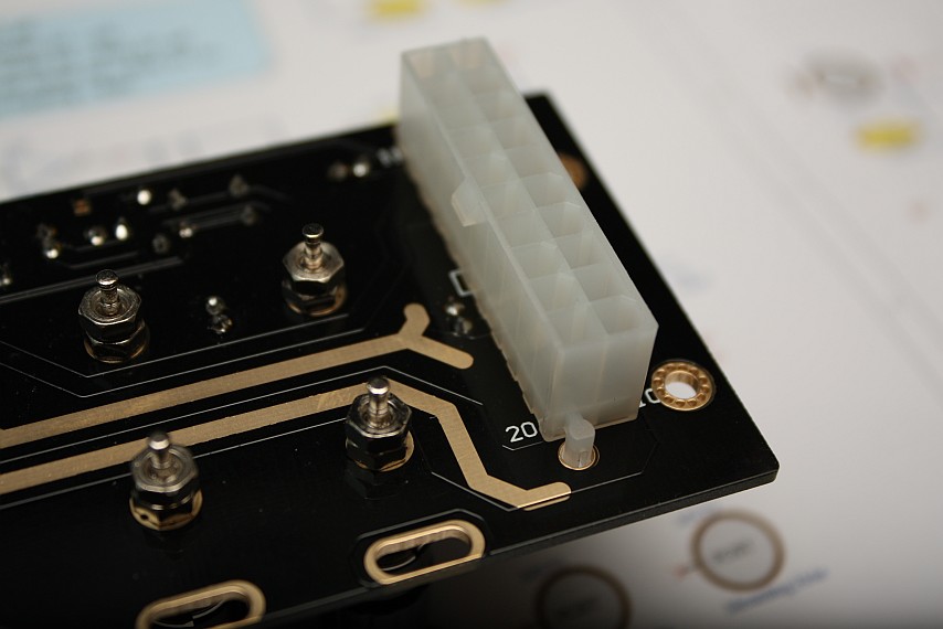
You can see clearly here the plated slots I designed in around the edge – these are for clipping alligator leads onto, and the silkscreen text indicates the output of each one. The plated-through holes designated K3 to K14 are for bolting the back conductive end of the banana socket / binding post onto. Notice the used of multiple vias in a circle around each of these and also the mounting holes – these offer increased strength for tightening up screws over them, and also for the binding posts a good low-resistance current path through the PCB.
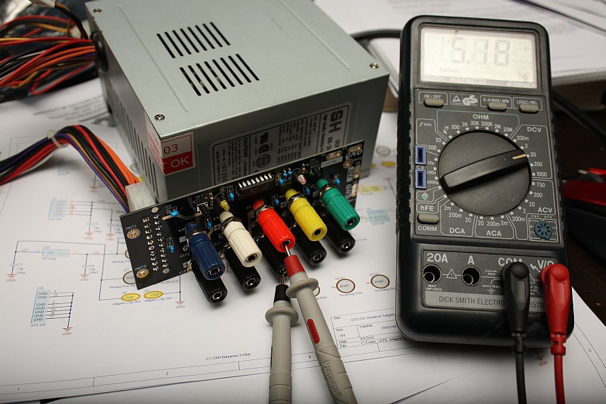
Below is the final assembled prototype:
The final image shows all the components clearly. All the capacitors provide a bit of decoupling for the different supply outputs, except C2 which is for de-bouncing the on-off circuit. All the others are ceramic 100nF caps. R1 and R4 are LED dropping resistors and R2/R3 form the feedback paths for the on/off dual-inverter latch.
I have now been using this board extensively at work and at home, powering several development kits off a single ATX supply (at work I have a Nanoboard-II and two Nanoboard 3000 FPGA development boards running at once, as well as a few other things). It has really simplified things well for me!
|
|
|
|
|
|
|
|
|
|
|
|